System Design and Architecture
- Fajr Fradi (Unlicensed)
- Enrico Bonaiuti
System Architecture
The system architecture is based on AWS services, Free and Open Source Software innovative technologies, supporting large web computing.
Hardware Architecture
GeOC is hosted on Amazon Web Server with the following specification:
Hosting provider
|
The technical implementation of the GeOC interface consists of four primary steps:.
- Web Interface
- Web Server
- Database Server
- Map Server (Geoserver/ArcGIS for Server WMS and ArcGIS for Server Imagery Service)
The GeOC application uses HTML forms and JavaScript to communicate with Java REST API on the web server. The REST API are used to process users request and communicate with the database by extracting the requested data and prepare the results in the requested format. If the user chooses an interactive visual, the data is sent to GeoServer/ArcGIS Server, which prepares the data to be displayed on the website using Leaflet/ Open layers.
A schematic representation of the process is shown below:
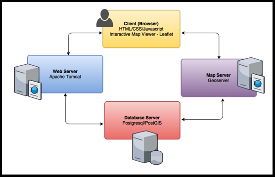
Figure 1 : Schematic representation of the GeOC implementation
Performance Hardware Architecture
GeOC has no dedicated hardware to enhance the system performance, nothing of the following were implemented: load balancer, CDN, clusters, however it is implemented on AWS.
Software Architecture
These are the GeOC components and libraries:
- Leaflet API
- Open Layers
- Smart Admin
- JavaScript
- Spring 4.3.x and Java REST API
- PostgreSQL 9.5
- PostGIS 2.2
- GeoServer 2.9.1
- ArcGIS Server
- Encoding: UTF-8
UTF-8 (8-bit UCS/Unicode Transformation Format) is a variable-length character encoding for Unicode. It is the preferred encoding for web pages.
Internal Communications Architecture
MEL System components interact with each other in systematic, specific ways. Their definition depends on either Zend Framework logic itself, or a customized way built for a custom feature in the system (i.e. Open Access repository). These internal interactions are exemplified below with code snippets. Below is a static representation of the subsystem composing the GeOC application:
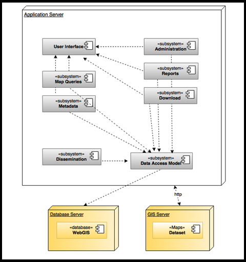
Figure 2: GeOC component diagram
The communication between the Application Server and the Database Server is the standard JDBC interface. Similar to the former, the communication between the Application Server and the GIS Server is presented in the diagram. The communication between the User Interface, Application Server, Database Server and GIS Server are more articulated and are explained more in detail in the following sequence diagram:
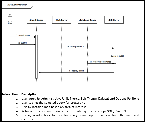
Figure 3: GeOC Map Query Interaction UML Diagram
System Architecture Diagram
The following diagram illustrates the high-level architecture of the GeOC application main components, including user interaction with the system and the dissemination systems:
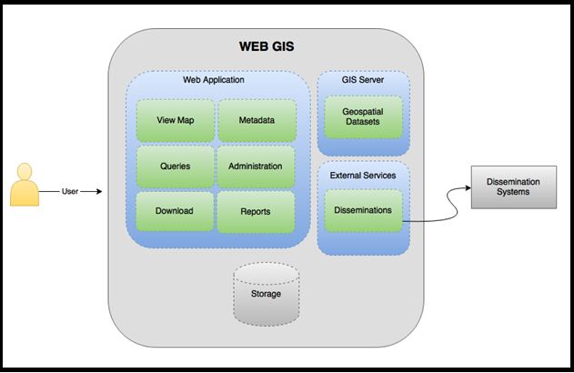
Figure 4: GeOC high-level architecture design
System Design
Business Requirements
The following table represents MEL System business processes with a detailed description of actors, process flow, and requirements.
Table 1:Business Process : GeOC sharing, managing and disseminating
Actors |
|
Process Flow |
|
Requirements |
|
Database Design
A physical GeOC data model (GeOC-PDM) is provided in a HTML format file named Full GeOC Physical Report.html. The file supports the analysis and documenting of the underlining tables, views, and other objects in a database, including the multidimensional objects necessary for data warehousing. A PDM is more solid than a conceptual (CDM) or logical (LDM) data model. You can operate by modelling, reverse-engineering, and generate on all the most popular DBMSs.
A physical GeOC data diagram provides a graphical view of your database structure, and helps to analyze its tables (including related columns, indexes, and triggers), views, and procedures, and the references between them.
Here are some parts of the GeOC data model:
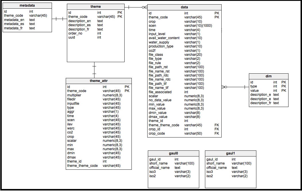
Figure 5: GeOC Data Model
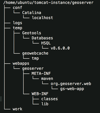
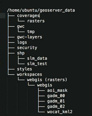
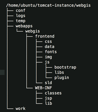
File and Database Structures
The following figures describe the usage cases for each directory:
GeoServer Directory Structure | GeoServer Data Directory Structure | GeOC Directory Structure |
|---|---|---|
|
|
|
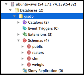
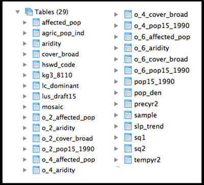
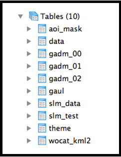
Database Management System Files
GeOC system database consists of independent and dependent tables, in order to store and split system data.
Database: gisdb Schema: rasters, slm, GeOC | Schema: rasters | Schema: GeOC |
|---|---|---|
|
|
|
Non-Database Management System Files
MEL has two backups tasks performed, and are done as follows:
- A server level backup policy (daily).
- A full local database backup (every 30 Minutes)
Database Information
GeOC as a single database hosted on Amazon Web Server with the following specifications:
- Database name: gisdb
- Database instance: Amazon Ubuntu linux
- Database host: 54.171.74.139
- Database user name: postgres
- Database password: adm-aws001
- Current database size: 50GB
User Interface Design
GeOC User Interface consists of: header, top menu, content, side bar, user login area, download button and other buttons and tables as shown below:
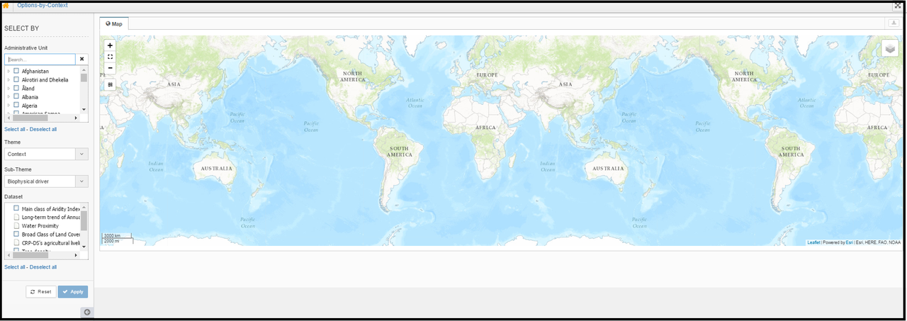
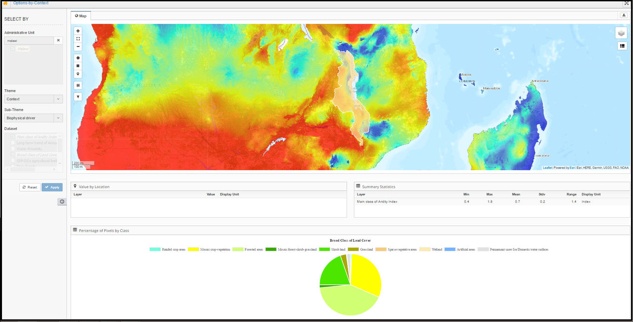
Figure 6: GeOC User Interface
Operational Scenarios
Data Flow Diagrams
The data flow diagram illustrates how data moves through the GeOC application, from where the data comes and where it goes and how it is stored in the three use cases: account management, query and submission of SLM.
Use Case 1: Manage the user account
To receive a user account, a request must be sent to an administrator. Once the request is approved, the user will be able to manage the settings and the assigned profile, which can always be edited by an administrator.
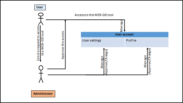 Figure 8: The User account management.
Use Case 2: Query of SLM
In the process of the query, the user needs to specify the administrative unit, theme and related sub-theme. Therefore, several datasets will be available for selection and visualization on the map. The query is not processed live and must be triggered with the button "Apply".
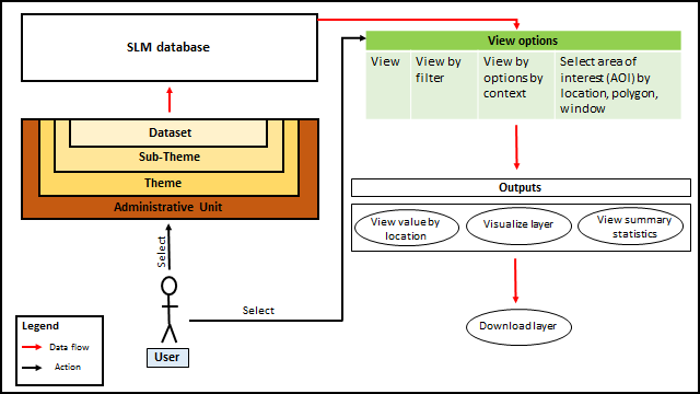
Figure 8: The query process.
Use Case 3: Submission of SLM
In the process of submission of SLM, the user needs the approval of an Admin in ordor to integrate his submitted SLM into the SLM database. The Admin user has the right to approve, edit or initiate a discussion about the submitted SLM with the user who submit it or the other user.
The process of SLM submission implies that an Admin will review the proposed dataset. Admins can approve, edit, reject or initiate a discussion about the submitted SLM with the submitter or other users.
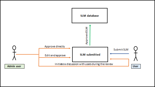
Figure 9: Submission of an SLM dataset.